|

Stan Thompson
| |
[ Uranium Fuel ] [ Breeding Pile ] [ Bad Shit ] [ SGT's Facilities ] [ SGT's Process ] [ Michele Gerber ]
Thompson's Facilities
From: PLUTONIUM PRODUCTION STORY AT THE HANFORD SITE:
PROCESSES AND FACILITIES HISTORY (Document Number WHC-MR-0521
)
by Michele Gerber, Ph.D. and is
available to download.
Thumbnail images have been added to Gerber's text by the Webmaster.
Click on the thumbnail for a full sized image.
4.0
RADIOCHEMICAL SEPARATIONS PROCESSING
AT THE HANFORD SITE
4.1
THE BISMUTH-PHOSPHATE PROCESS
4.1.1
Start-up of Radiochemical Processing at HEW
The earliest radiochemical processing operations at the Hanford Engineer
Works using "hot" (irradiated uranium) feed began at the 221-T Cell
Building, also known as T-Plant or T-Canyon, on December 26, 1944.
This event was historic because T-Plant was the first full-size
radiochemical processing plant in the world.
The only previous radiochemical processing of irradiated uranium fuel
elements had been done on an experimental scale at a facility known as the
Clinton Semi-Works (or SMX), located at the Clinton Engineer Works in Oak Ridge,
TN.[lxxxv]
4.1.2
T, B, and U Process Groups
The original separations process used at HEW was the bismuth-phosphate
(BiPO4) process. It was based
on the principle that bismuth phosphate is similar in crystal structure to
plutonium phosphate. The entire
operation was a batch, precipitation process that achieved separation by varying
the valent state of plutonium 239 (Pu-239), and then by repeatedly dissolving
and centrifuging plutonium-bearing solutions.
The steps of the bismuth-phosphate process were carried out first in T‑Plant,
then in the 224-T Bulk Reduction Building, and then in the 231-Z Isolation
Building. A second and third
set of facilities for both the first and second phases of the BiPO4 process also
were built at HEW, but the final steps always took place in the 231-Z Building.
The second set of facilities was known as the B Process Group, and
consisted of the 221-B (B-Plant) and 224‑B Buildings and their
associated support structures. B-Plant
began processing irradiated U at Hanford on April 13, 1945.
The third set of facilities was known as the U Process Group, and
consisted of the 221-I (U-Plant) and 224-U Buildings and their associated
support facilities. The U Process
Group never handled irradiated uranium, but served as a training facility until
another use for the buildings was developed in 1952.[lxxxvi]
4.1.3
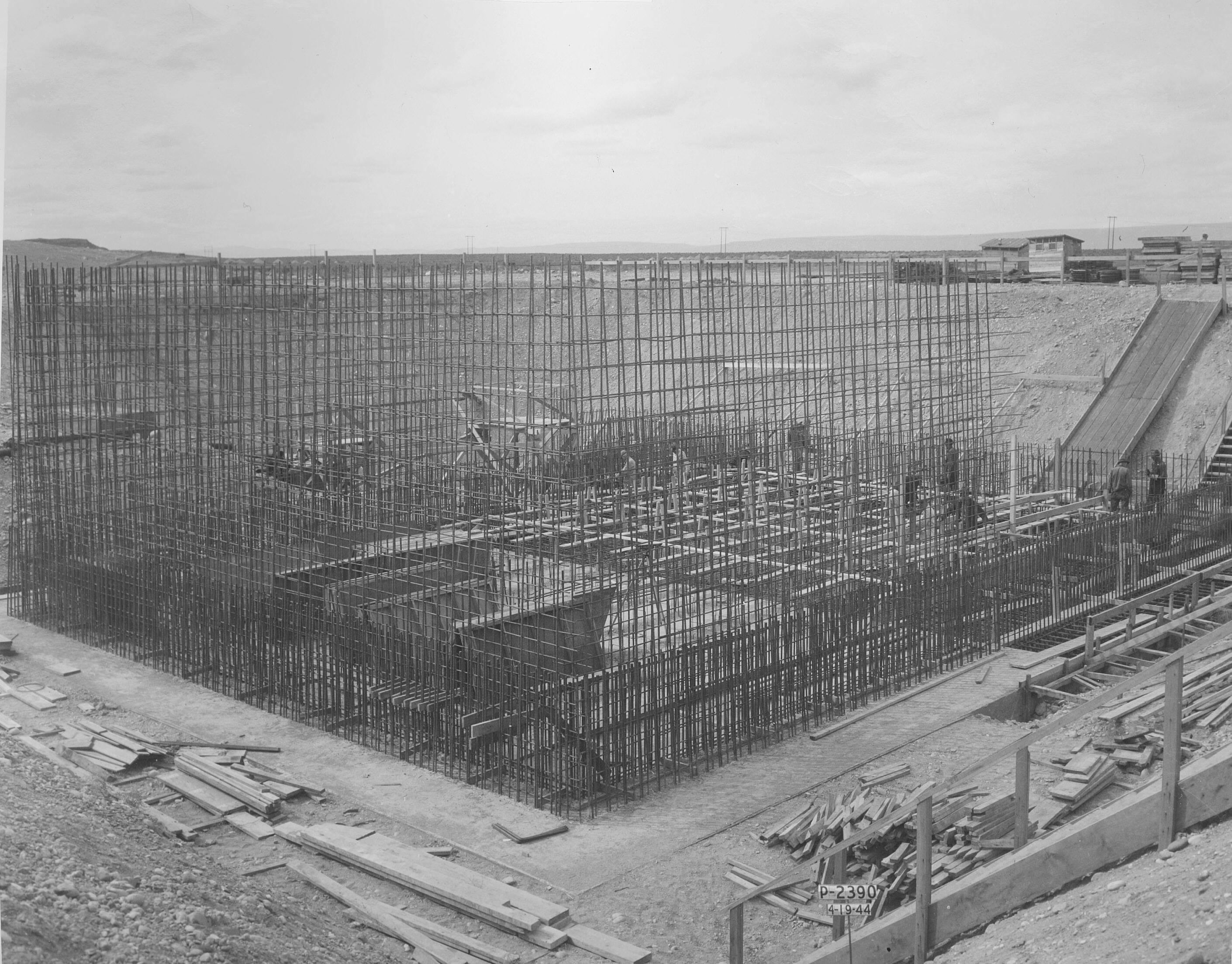
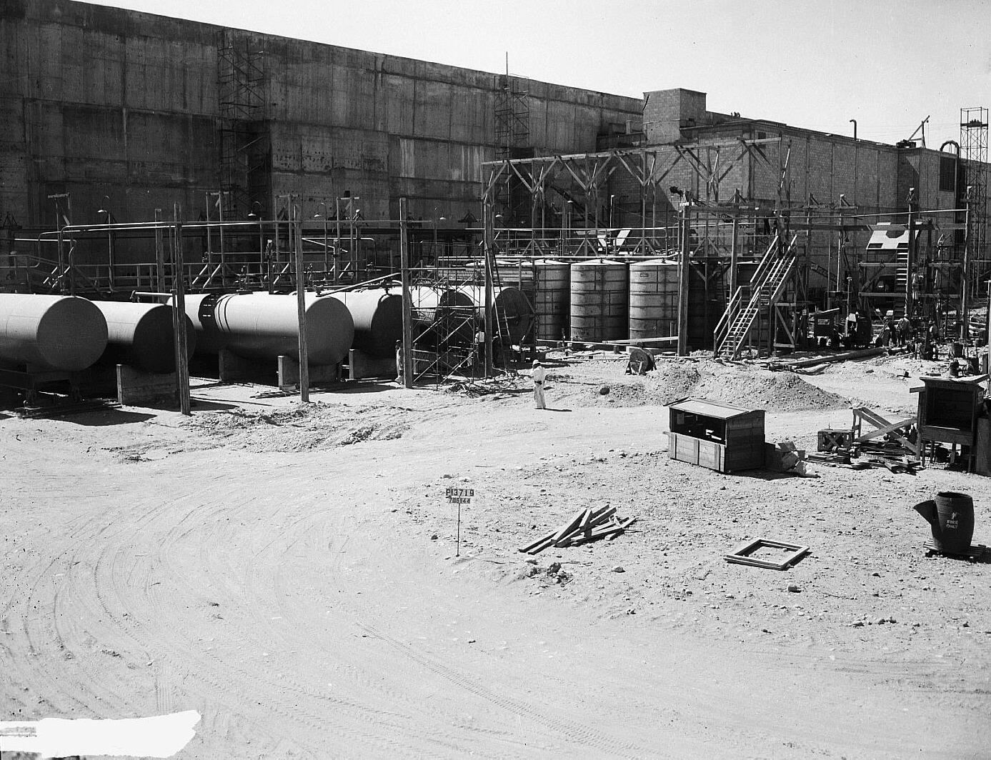
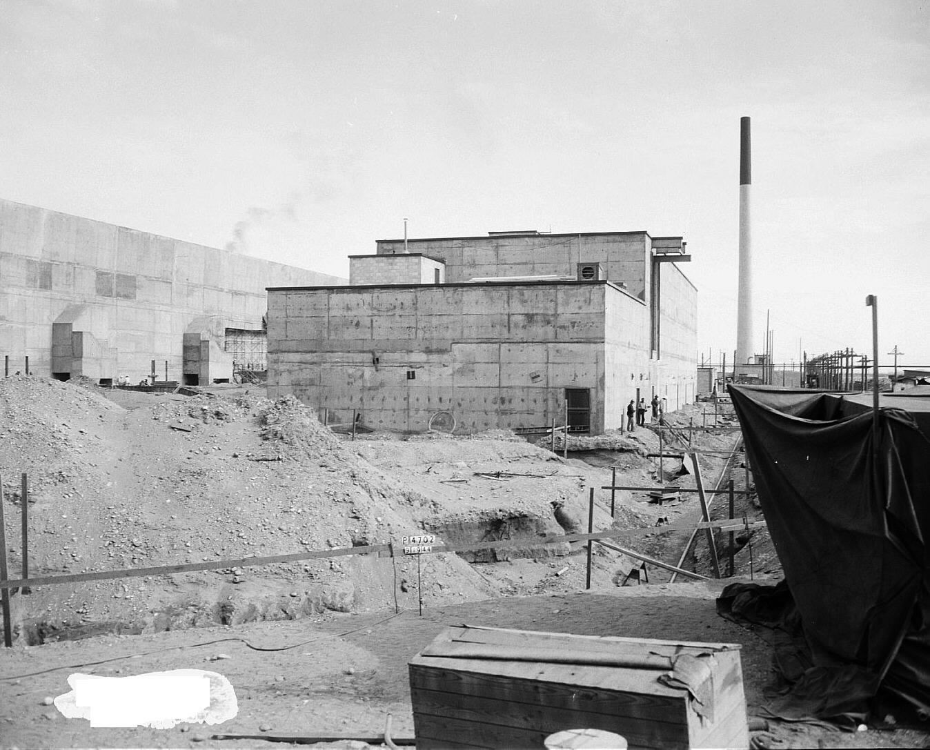
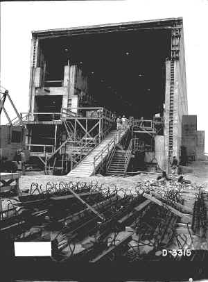
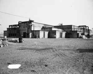
Original Separations Buildings
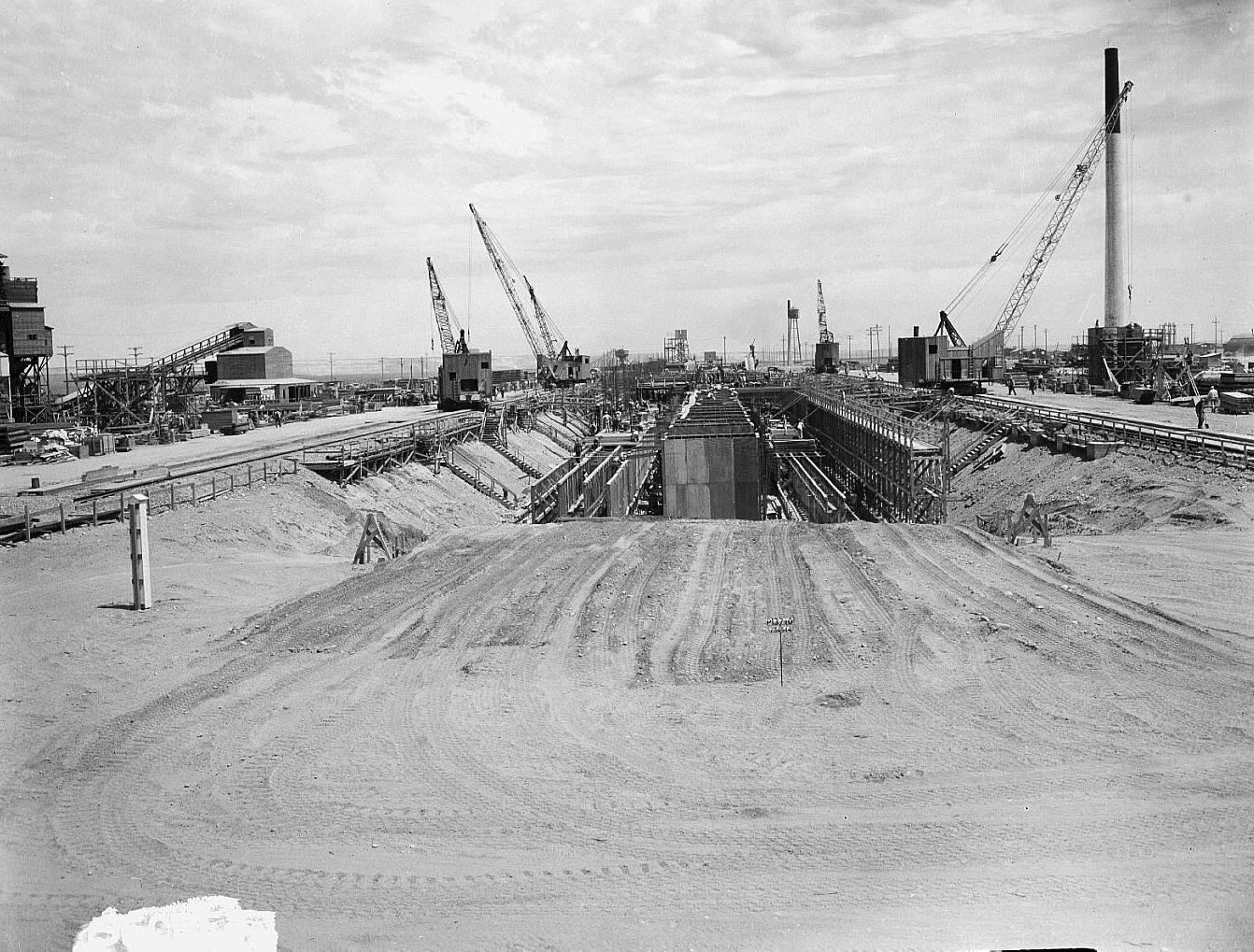
The 221-T Cell Building originally was
85
feet (25.91 meters) wide by 875.5 feet (266.85 meters) long by 102
feet high.
It was a dense, thick, reinforced concrete, rectangular mass,
approximately one-quarter
below grade, with no windows.
At the time that T-Plant was built, its design and construction was
described by the DuPont Corporation builders as "extremely unusual...due to
process requirements. In other
words, once the equipment in any of the cells is placed in operation, it will
not be possible to approach it for maintenance or to manually remove or fit up
piping." Remote
operational requirements, as well as radiation shielding requirements, resulted
in the 221‑T Building being unique, and a first-of-a-kind structure
in the world, when it was built.
The
221‑B Building was virtually identical to T-Plant,
except that it had 65 feet (19.81 meters) less length and did not contain a
special head-end testing laboratory that was included in T‑Plant.


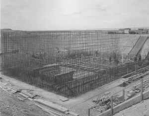
The foundation of each canyon building structure was a reinforced
concrete pad
varying from six
to eight feet (1.83 to 2.44 meters) in thickness
with a spread footing. Outside
building walls were likewise reinforced concrete three
to five feet (0.91 to
1.52 meters) thick.
The barricade wall between the cells and canyon and the galleries was seven
feet
(2.13 meters) thick.

Each
building had a suspended flat concrete roof varying from three
to four feet (0.91
to 1.22 meters) in
thickness.
Construction joints were provided between each building section and
expansion joints at frequent intervals. The
inside surfaces of the cells and pipe trench, removable cover blocks, the deck
floor level in each canyon, and each second floor control gallery were painted
with "Amercoat,"
an epoxy-based contamination fixant sealant, to reduce the porosity of the
concrete surfaces.
Each 221 Building structure was separated into two main portions -
Galleries and Canyon, with the inside of the building being divided into 22
sections (for T-Plant) and 20 sections (for B-Plant).
Each section encompassed two cells.
Sections were 40 feet (12.19 meters) long with the exception of
Sections 1, 2, and 20, which were 44 feet (13.41 meters), 43 feet
(13.11 meters), and 43.5 feet (13.26 meters) respectively.
Inside the head-end of T-Plant, were two developmental equipment cells, A
and B, having the same length as cells 1, 2, 3, and 4 [a total of 65 feet
(19.81 meters) in length]. The
essential difference between this testing laboratory and a standard T-Plant
section was that each testing laboratory cell contained the equipment
corresponding to that in two standard cell sections.
The head-end laboratory section also included a continuation of the
basement, first and second floor galleries that ran the length of T-Plant.
However, these galleries turned at the head-end and continued across to
the rear wall of the building.
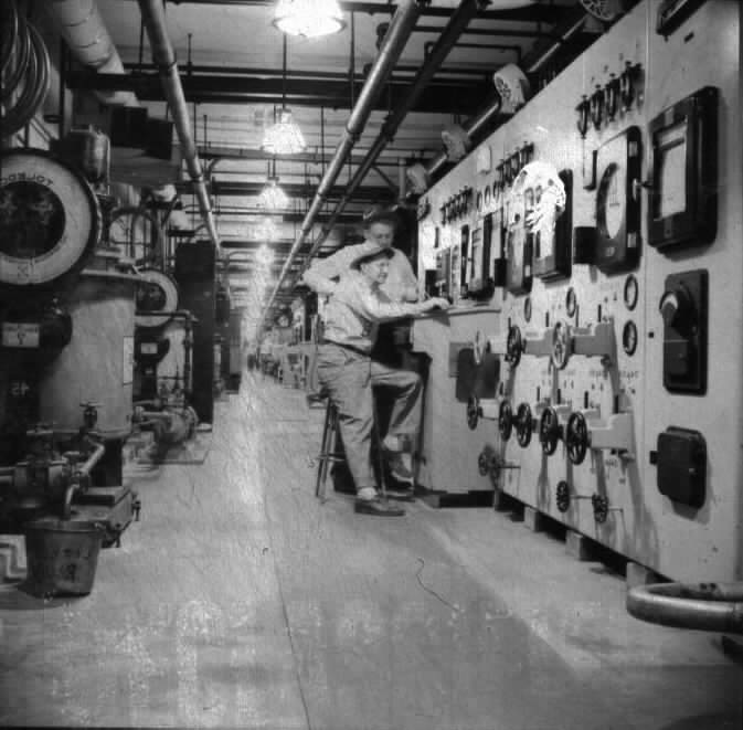
4.1.4
Galleries
The HEW canyon buildings were so designed that the control panel boards,
chemical and service distribution, were located in three galleries, one above
the other along the "front" side of the building; the west side in the
case of T-Plant and the north side in the case of B-Plant.
The first gallery, at the basement level, was used principally for
electrical distribution and control cabinets.
The first floor gallery consisted of a piping loft containing steam,
water, air, and chemical headers as well as piping connections between the panel
boards and weigh tanks on the second floor and through-wall cell piping.
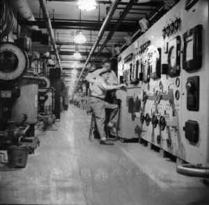
The second floor gallery was the control center for the cell equipment,
and was known as the operating gallery. Each
40-foot building section constituted a separate unit, and were controlled by
separate gauge boards in the operating gallery.
The gauge board panels were installed in a row along the barricade wall
between the canyon and the galleries, with weigh tanks along both front and back
walls of the gallery.
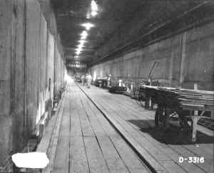

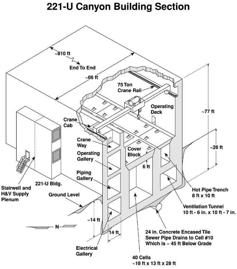
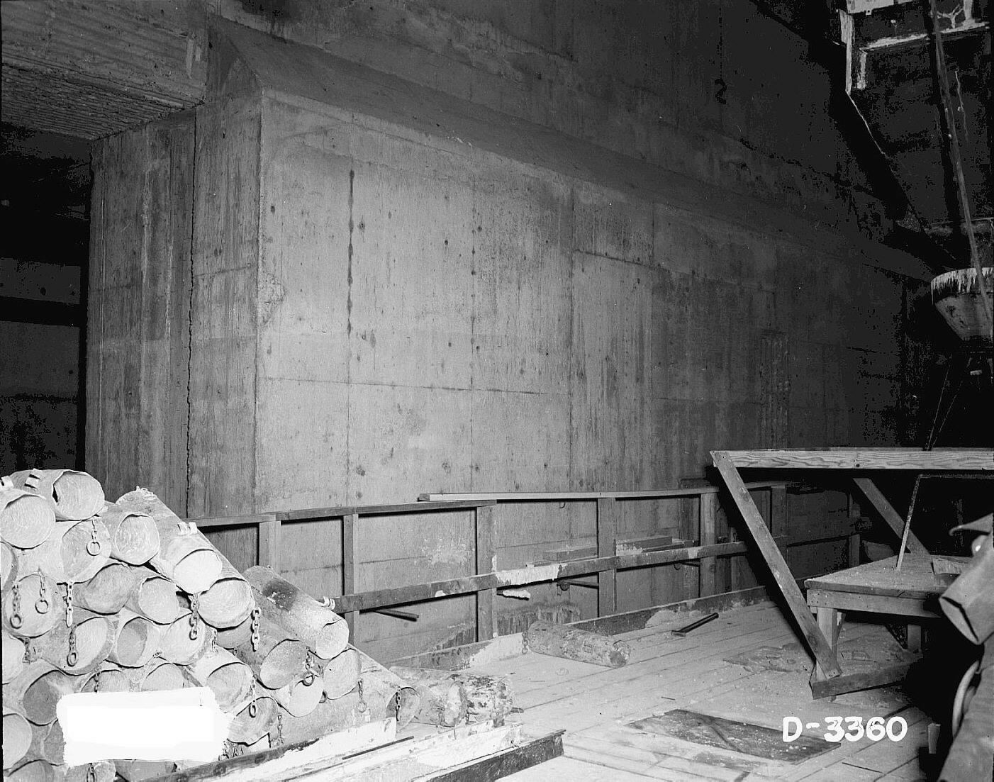
4.1.5
Canyon
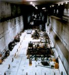
The lower portion of the canyon below the "deck" (ground) level
contained 40 individual concrete cells having removable concrete cell-block
covers. The cell covers were
constructed with overlapping, step-wise edges, to contain the radiation within
the cells. A 10-foot (3.05‑meter),
6‑inch (15.24‑centimeter) square exhaust duct ran along the back
wall of the building paralleling the bottom of the cells and was connected by an
underground concrete duct to the 291 Exhauster Buildings and Stacks for the
removal of cell fumes. Immediately
above this duct was a pipe trench which also paralleled the cells, containing
inter-connecting cell piping. The
pipe trench was also covered with removable, sectional concrete block covers.
The construction of the cells was standardized as much as possible, to
ease the maintenance problems as much as possible.
The sections having standard designs were 4, and 6 through 20.
Section 1 differed in that it was a large cell with two long openings for
the immediate storage of partially processed material.
Section 2 contained two long openings of the same size, one of which
centered over the railroad track where irradiated fuel elements were brought
into the building, and the other which housed initial cell equipment.
A reinforced concrete railroad tunnel, extending 150 feet from the front
sides of the buildings provided rail service to this section.
Section 3 differed in that the pipe trench ended opposite cell #5.
Section 5 differed in that cell #10 was much deeper, because it served as
a collection point for drainage to the sewer section.
At T-Plant, the head-end sections differed in that the pipe trench
terminated in a manner that would allow for future extension of the building if
desired. (Such extension did not
happen.)
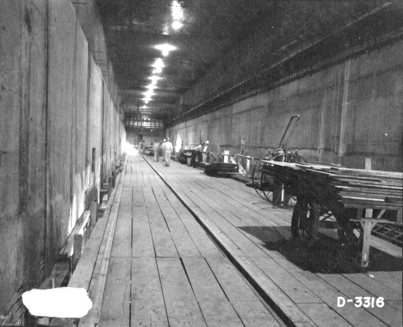
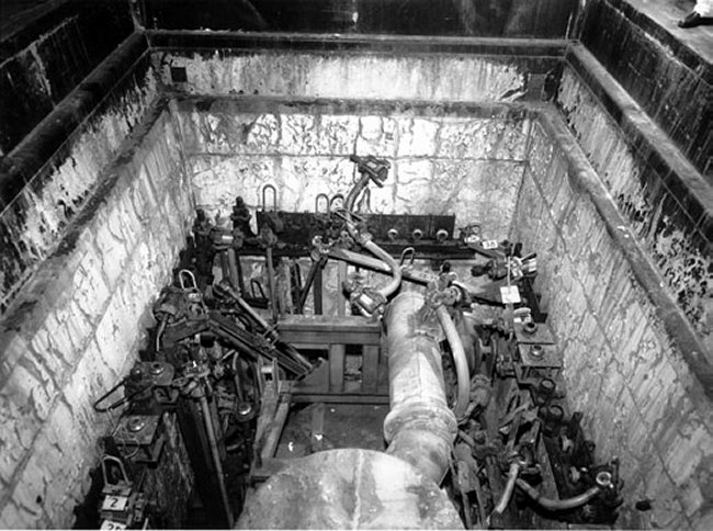
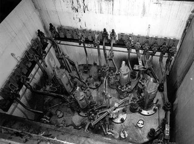
4.1.6
Processing Equipment
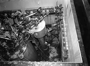


The equipment installed in the cells consisted mainly of centrifuges and
vessels with and without agitators, and connecting piping between cell walls and
equipment. Around the periphery of
each cell were 42 flanged piping connections serving the cell equipment.
Special piping connectors were used allowing pipes, conduits, and
instrument leads to be connected by tightening a single nut.
Vertical connectors were used for electrical connections only, and
horizontal connectors were used for piping and instruments only.
The canyon portion of each Cell Buildings was served by an overhead
bridge crane equipped with 75-ton and 10-ton hooks as well as four independent
monorail hoists of one and one/half-ton capacities.
The crane cab was designed to contain special controls, observation and
communication facilities in order to remove cell blocks, cell equipment and cell
piping by remote control. The
canyons also each contained a second overhead bridge crane, 10-ton capacity for
maintenance use only, when the building was completely shut down.
4.1.7
Stair Towers
Four-story reinforced concrete stair towers were constructed along the
front side of each 221‑T Building (eight in T-Plant and seven in
B-Plant) to provide access to the three gallery levels and the crane-cab runway.
These stair towers also housed heating and ventilating equipment and rest
rooms for the galleries. Reinforced
concrete labyrinthed stair towers were built along the rear sides (east side in
the case of T-Plant and south side in the case of B-Plant), to provide access to
the canyon portion of each building at the deck level.
T-Plant had ten such rear stair towers and B-Plant had nine.[lxxxvii]
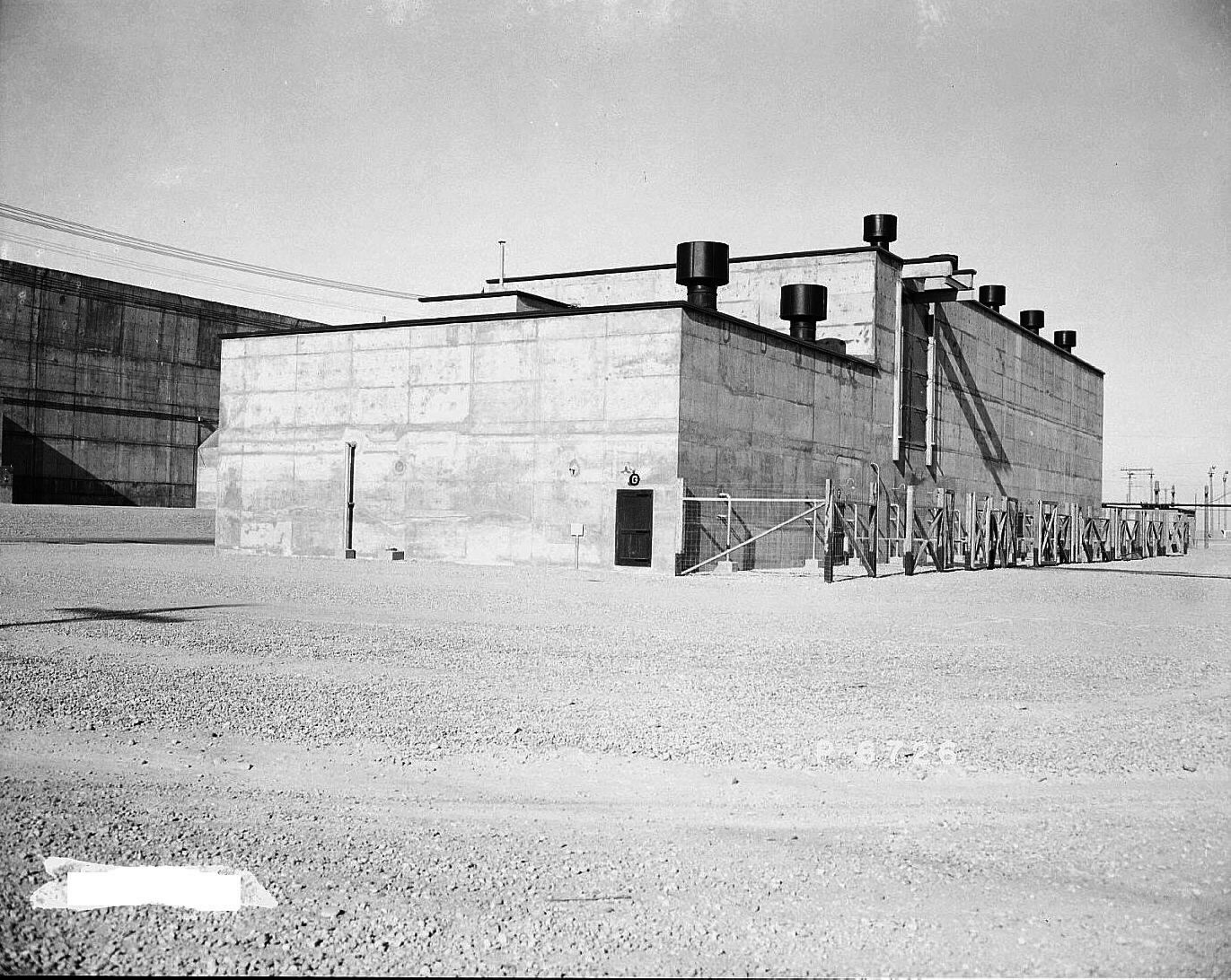
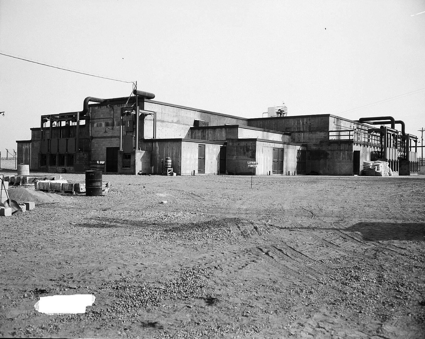
4.1.8
224 Bulk Reduction Buildings
The 224 Buildings were constructed of reinforced concrete.
Each was a three-story frame structure with concrete and concrete block
exterior and interior walls. The
front of each 224 Building was placed precisely 150 feet from the back of its
corresponding 221 Building, and in line with the front of its process
group's 222 Control Laboratory. Each
224 Building contained a total of 21 rooms not including two stair towers, one
closet, one janitor's closet, and an elevator "penthouse."
The overall dimensions were 60 feet (18.29 meters) 1 inch
(2.54 centimeters) by 197 feet (60.05 meters) long, with a total area
of 11,982 square feet (1 113.16 square meters).
Each building was 40 feet (12.19 meters) high for the majority of
its length, but reached higher elevations over two stair towers and over the
small penthouse area.


The foundation of each 224 Building was comprised of reinforced concrete
walls with spread footings, reinforced concrete piers and beams, and concrete
pads. Each floor slab was
reinforced concrete 4 to 12 inches (10.16 to 30.48 centimeters) thick.
Each roof consisted of flat reinforced concrete 5 to 12 inches (12.70 to
30.48 centimeters) thick, covered with built-up felt, gravel surfaced
roofing, and containing 8 wood frame ventilators with meters.
The roof slabs were removable, so as to allow the movement of large
equipment pieces in and out.
Each 224 Building was essentially divided into two main sections:
the process cell section, and the office and operating gallery section.
The back side of the main structure contained the process cells and had
one foot thick concrete walls with a balcony running around three sides.
The 27-foot (8.23‑meter) by 197-foot (60.05‑meter) process
cell area contained five cells known as Cells A to E inclusive.
These cells were served by a hand-operated overhead crane.
Cells A through D measured 27 feet (8.23 meters) by 28 feet
(8.53 meters). Cell F measured
25 feet (7.92 meters) by 51 feet (15.54 meters), was L‑shaped,
and had an office in one corner of it. A
glass enclosure was located in the cell against this office wall, where the
partially finished product was collected for transfer to the 231-Z Isolation
Building. In Cell C, the right-hand
portion was a pit which connected with an underground pipe tunnel that ran from
the center line of Sections 13 and 14 in the corresponding 221 Building to each
224 Building.
The floors in the cells were sloped to a trench along the wall, for
gravity delivery to waste collection tanks.
The walls and floors in Cells A through E, and walls, floors, and
ceilings in F Cells and its office were painted with Amercoat.
A mezzanine floor extended across the side facing the corresponding 221
Building. Gauge boards and weigh
tanks used in connection with Cell F were mounted on this mezzanine.
One-foot (0.30‑meter) thick interior walls divided the process cell
section of each 224 Buildings from the office and gallery section.
The "front" (offices and gallery) side of the main structure
was reinforced concrete frame with 8-inch (20.32‑centimeter) concrete
block panels and 8-inch (20.32‑centimeter) and 4-inch (10.16‑centimeter)
concrete block partitions. An
elevator was installed adjacent to the No. 1 stair tower and was provided with
an outside concrete loading platform to facilitate the movement of chemicals to
and from trucks. The first floor
contained offices, a chemical storage room, and other service rooms.
The second floor was principally a pipe loft containing five concrete
vestibules opposite each centrifuge platform.
All chemical and service lines entered the building on this level.
The third floor was an operating gallery that contained gauge boards,
tanks, and instruments.[lxxxviii]
4.1.9
231 Isolation Building
The 231-Z Building was located in the western portion of the 200-West
Area of the Hanford Site, midway between T-Plant and U-Plant.
Originally, this structure was a two-story, flat roofed, reinforced
concrete, frame building with 8‑inch concrete block panels and 4‑inch
(10.16‑centimeter) and 8‑inch (20.32 centimeter) concrete block
partitions. Overall dimensions were
147 feet (44.8 meters) by 189 feet (57.61 meters) 10‑inch
(25.40 centimeters) by 24 feet (7.32 meters) 6‑inch
(15.24 centimeters) tall, with a total of 27,964 square feet
(2597.94 square meters). A
one-story ventilation and equipment room ran along the west end of the building.
The 231-Z facility had no windows.
In World War II, the 231-Z Facility contained a total of 57 rooms
including 20 laboratories, several process and chemical receiving and
storage rooms, offices, change room facilities designed to accommodate 190
employees, air conditioning equipment, a distilled water system, ventilation and
exhaust systems, and a compressed air system.
Six of the laboratories were known as "cell laboratories," and
served as the major centers where the actual Pu isolation process was carried
out. All of the rooms except for
one rest room were located on the first floor, with the second floor serving as
a pipe and service loft containing duct work and filters for the ventilation and
exhaust systems.
The interior of the 231-Z Building was configured with two 8 foot
(2.44‑meter) wide, north and south corridors, A and B; one on each side of
the (6) cell laboratories with emergency exits to the outside of the building.
Corridors C and D ran east and west, connecting with corridor B.
Corridors E and F ran north and south separating laboratories and
intersect corridors C and D. Two
concrete stairways led to the second floor, and below-grade piping led to a
waste disposal system. This piping
was modified in 1948 to achieve additional control of 231-Z process wastes.
The 231-Z Building foundations consisted of reinforced concrete piers
with spread footings and concrete walls with spread footings.
Floors were reinforced concrete varying from 4‑inches (10.16‑centimeters)
to 12‑inches (30.48 centimeters) in thickness.
The walls and ceilings of the cell laboratories and Vaults A and B were
reinforced concrete 1 foot thick. The
roof was likewise reinforced concrete 4‑inches thick and was covered with
built-up felt, gravel surface roofing containing numerous openings for intake
and exhaust ducts. The walls,
floors, ceilings, and equipment in rooms 1 to 6, 8, 27, 31 to 45, Vaults A and
B, and corridors A, B, C, D, E, and F were painted with "Amercoat" to
obtain non-porous surfaces.[lxxxix]
[lxxix].
Erickson, UNI-1437, Rev. 2, pp. 5-6, 10, V-1; Scott, UNI-1960, pp. 1-3,
13-17; Newby and Marshall, UNI-2109; Lyon, UNI-2110; Nelson, UNI-3422; Nelson,
UNI‑3329; Zaloudek and Ruff, UNI-3653 (PNL-5924); Zaloudek and Ruff,
UNI-38994 (PNL-5930); Lee, UNI-4193; Nelson, UNI-4191 Rev. 1; Alzheimer and
Gonzalez, UNI‑4285; Martek, UNI-4263; Lyon, UNI-1986; Cummings,
UNI-2063; Rainey, UNI‑2182; Conn, UNI-2227 Rev. 1; DeMaria, UNI-3481 Rev
1; Shoemaker and Fuller, UNI-21016; Reeves, UNI-610 Rev. 1; Lechelt, UNI-2925;
Lattin, UNI-3333; Rasmussen, UNI-3583; Stauch, UNI‑4210; Linschooten,
UNI-4148; Pope, UNI-4239; Smith, UNI-4253; Sullivan, UNI-4225.
[lxxx].
Hanford Engineer Works, HW‑10475‑B, pp. 910-919.
(Note: The exact fuel
storage times used in World War II are not known.
Following the war, storage times lengthened in order to allow for
additional decay (stabilization) of radioisotopes such as Iodine 131.)
[lxxxi].
Foskett, HW-18208; Stark, HW-22824.
[lxxxii].
Watson, Brendel and Shields, WHC0EP-0477.
[lxxxiii].
Harrison, DUN-7711.
[lxxxiv].
Nelson, UNI-2046.
|